The qspinlock is implemented on top of the mcs spinlock. The MCS stands for Mellor, Crummey, and Scott, the surnames of the creators. The main idea is to have each spinner spin on its own per-cpu variable, thereby avoiding the constant cacheline bouncing between different CPUs. Cacheline bouncing occurs when all CPUs spin-wait on the same lock variable, causing them to repeatedly read this variable. When one CPU unlocks, this variable is modified, invalidating the cachelines of all other CPUs, which then have to re-read the variable. This results in a performance overhead. The MCS lock mitigates this by having each CPU spin on its own dedicated variable, thus avoiding contention on a single lock variable.
This article does not delve into the evolution of spinlocks but directly explains the final implementation of the qspinlock.
If the text in images is unclear, you can right-click and select “Open Image in New Tab” for a high-resolution view.
Data Structure Definition⌗
The qspinlock structure is defined as follows:
typedef struct qspinlock {
	union {
		atomic_t val;

		/*
		 * By using the whole 2nd least significant byte for the
		 * pending bit, we can allow better optimization of the lock
		 * acquisition for the pending bit holder.
		 */
		struct {
			u8	locked;
			u8	pending;
		};
		struct {
			u16	locked_pending;
			u16	tail;
		};
	};
} arch_spinlock_t;
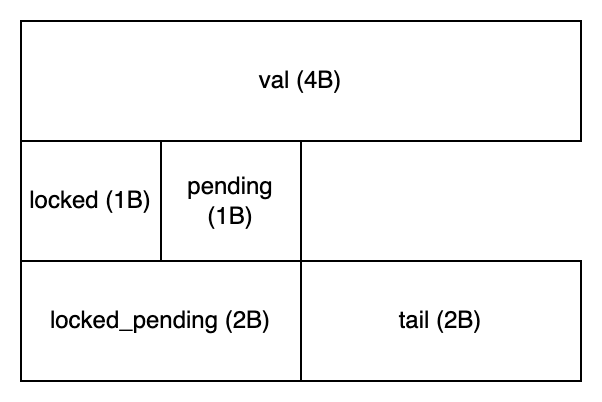
The memory layout is shown below. Note that a union type is used in the definition, so using the locked_pending variable allows simultaneous retrieval or modification of both locked and pending variables.
The CPU holding the lock is called the owner, and the waiting CPUs are termed spinners. These spinners can be further categorized based on their behavior into three types: pender, successor, and queuer. The term pender is a coined word to better illustrate the spinlock logic.
Locking and Unlocking Process Demonstration⌗
The locking and unlocking process is essentially a state machine. We’ll demonstrate the state changes graphically.
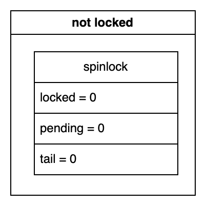
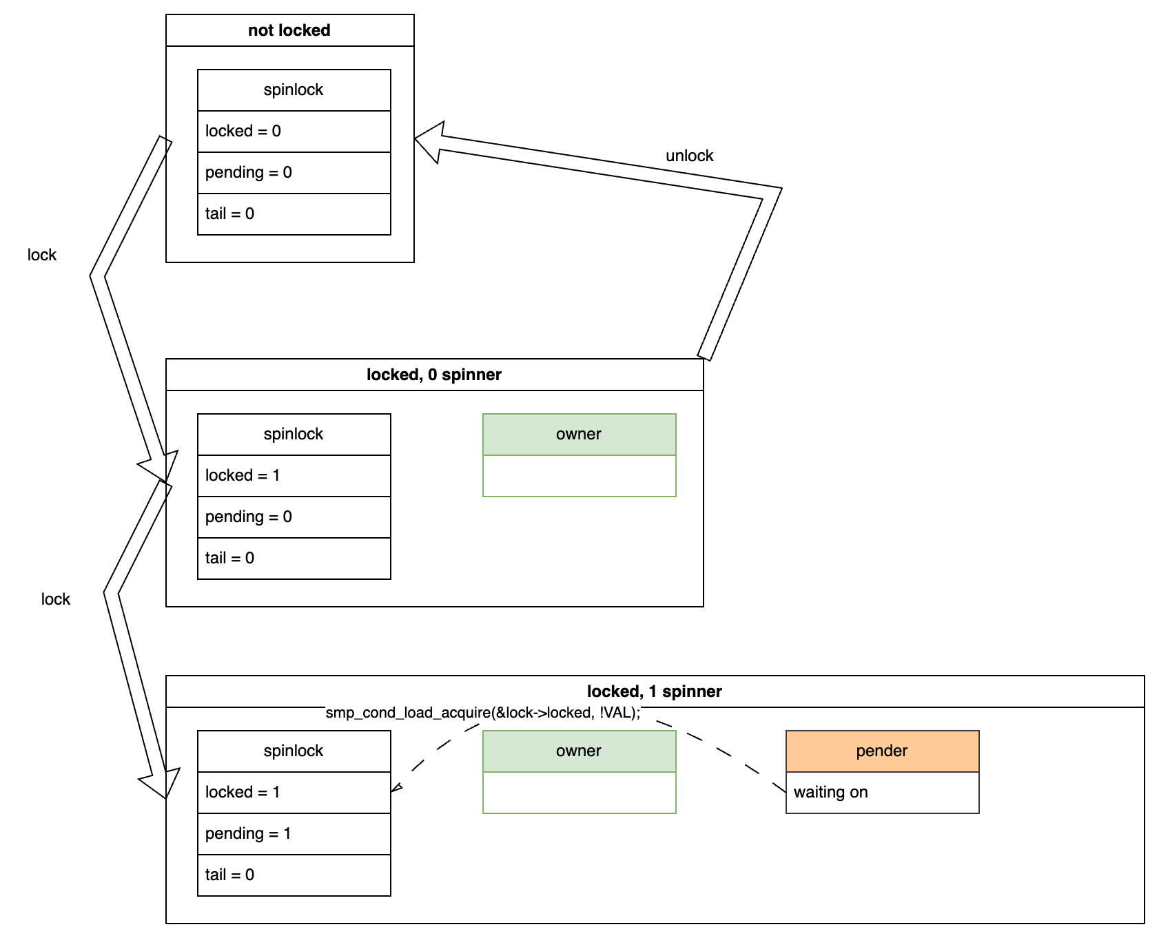
Initially, in an unlocked state, the structure members have the values shown below:
0 Spinner⌗
Locking⌗
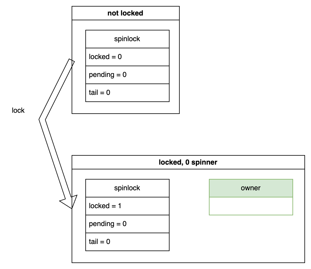
Now, let’s assume a CPU attempts to acquire the lock. Since no other CPUs are waiting, the state transitions as shown below. The spinlock->locked variable is set to 1, indicating that the lock is acquired. At this point, there is only an owner and no spinners.
Unlocking⌗
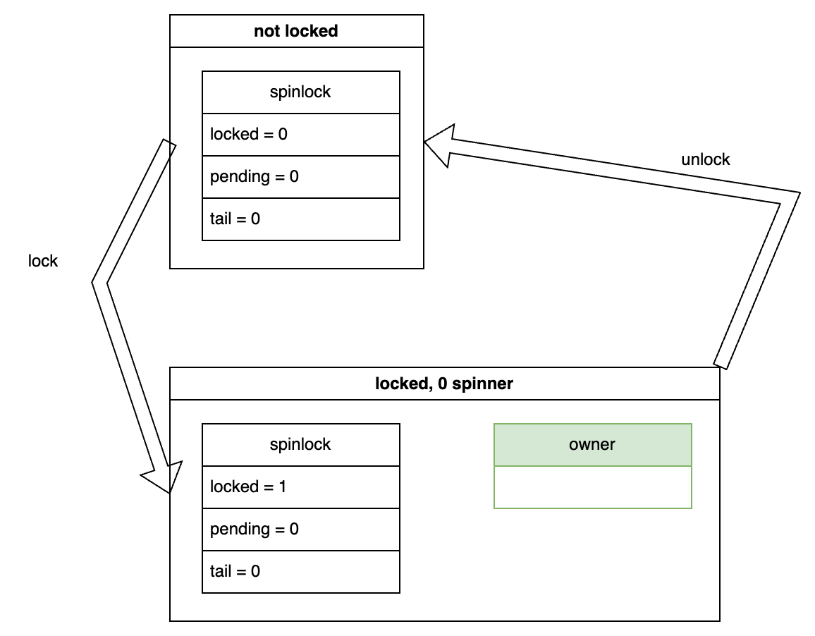
In this scenario, if the owner releases the lock, the state transitions back to the unlocked state:
1 Spinner⌗
Locking⌗
Assume that while the owner holds the lock, another CPU attempts to acquire it. This CPU will have to wait, and we call this waiting CPU a pender. The pender sets the pending variable to 1 to indicate its presence and then spins-waits for the spinlock->locked variable to become 0. The dashed arrow in the diagram indicates the waiting relationship and the corresponding code.
It’s worth noting that the pending variable is exclusive to the pender. If the pender disappears, the variable reverts to 0.
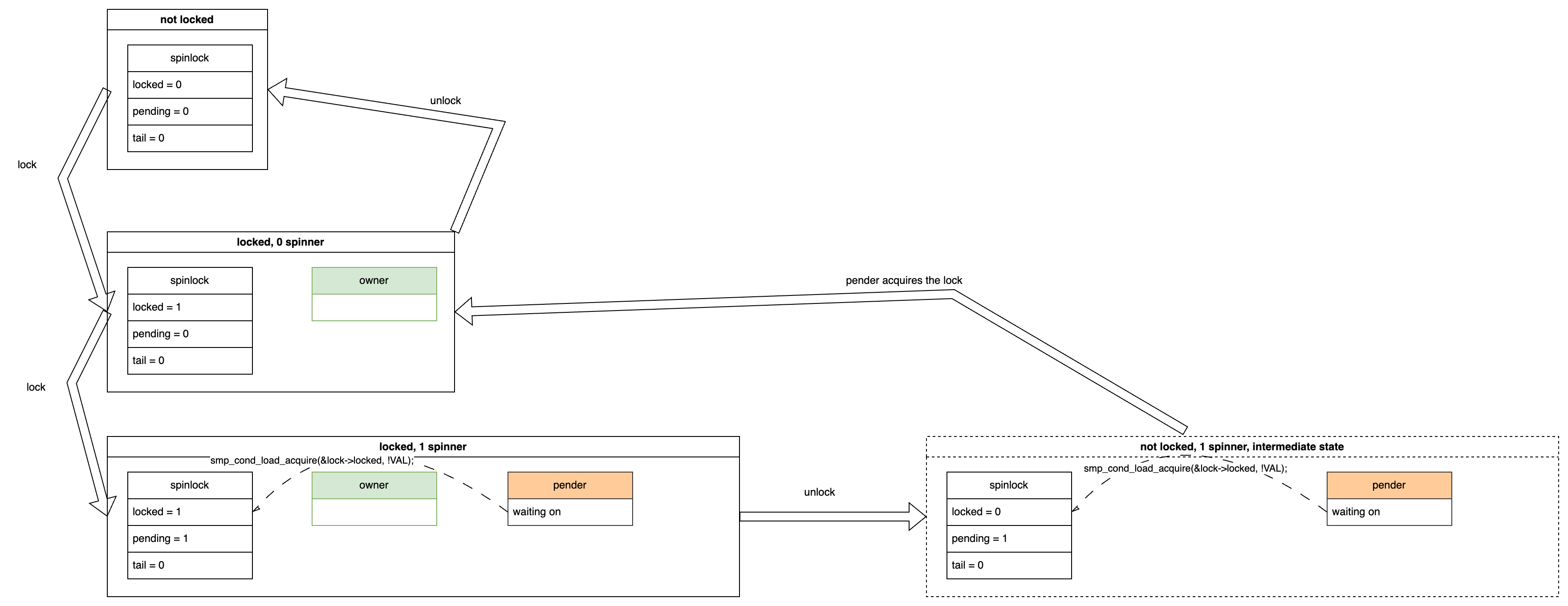
Unlocking⌗
In this case, if the owner releases the lock, two steps occur:
- The
ownersets thespinlock->lockedvariable to 0, indicating the lock is released. - The
penderdetects thatspinlock->lockedis 0 and atomically changes(locked=0, pending=1)to(locked=1, pending=0). Here, settinglockedto 1 signifies that thependerbecomes the newowner, and clearingpendingto 0 indicates thepender’s disappearance (as it has become theowner). As mentioned earlier, thependingvariable is an exclusive indicator for thepender.
The overall state transition for unlocking is shown below. The state within the dashed box on the right represents an intermediate state, where only the first step is completed. Once the second step is completed, the state transitions to the 0 spinners scenario:
2 Spinners⌗
Locking⌗
Let’s consider a scenario where, in addition to the pender, another CPU attempts to acquire the lock. This new CPU will spin-wait on both spinlock->{locked, pending} variables. We call this CPU a successor.
In this situation, the spinlock->tail variable stores the successor’s cpu id. The idx field in the diagram indicates the context (i.e. process context, softirq, hardirq, nmi) of this successor, but we can ignore it for our discussion. It’s enough to know that the tail variable “points to” the successor cpu. The arrow in the diagram indicates this pointing relationship starting from the tail to the successor cpu’s per-cpu mcs node structure. While the mcs node appears in this scenario, it hasn’t yet come into play. We will discuss it further later.
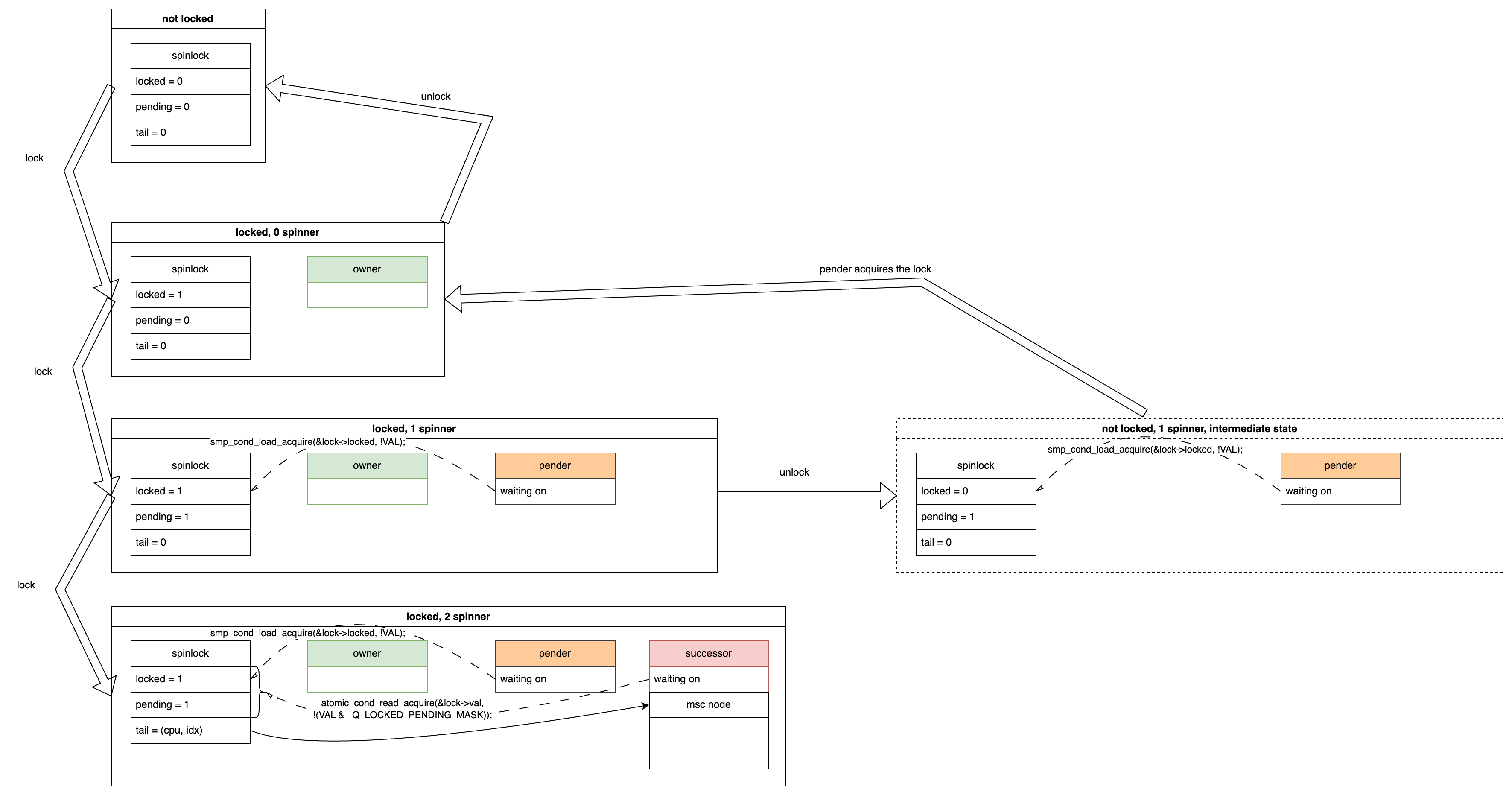
To summarize, in this situation, there are two spinners: the pender waiting for spinlock->locked to become 0, and the successor waiting for both spinlock->{locked, pending} to become 0.
Unlocking⌗
If the owner releases the lock, the owner disappears, and the pender detects that spinlock->locked is 0. The pender then atomically changes (locked=0, pending=1) to (locked=1, pending=0), becoming the new owner and indicating the pender’s disappearance (now the owner). [This part is the same as the “1 spinner” scenario]
The unlocking state transition is shown below. You can see that after releasing the lock, the pender becomes the new owner, and the pender disappears. However, the successor is still there, waiting for both spinlock->{locked, pending} to become 0.
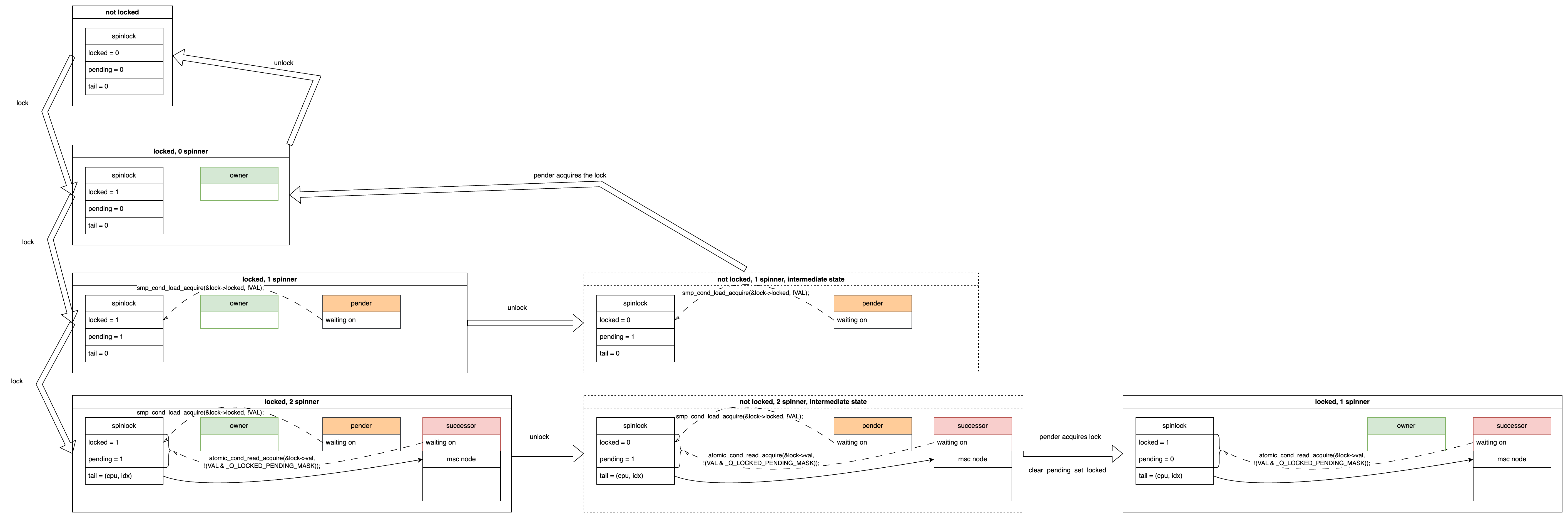
Next, if the owner releases the lock again, the spinlock->locked variable becomes 0, and finally, both spinlock->{locked, pending} variables become 0. The successor detects this change and atomically sets the spinlock->locked variable to 1, thereby acquiring the lock and becoming the new owner. The state transition is shown below:
At this point, you can observe a pattern: the pender and successor have equivalent statuses. Their next step is to become the owner, but they wait for different conditions. So why have two equivalent spinners? This is a small optimization, which we will discuss after explaining the overall process. For now, just focus on understanding the state transitions.
3 Spinners⌗
Locking⌗
Now, let’s make the scenario more complex. Suppose another CPU attempts to acquire the lock while the successor is waiting. This CPU will wait on its own per-cpu mcs node structure and is called a queuer.
Specifically, each CPU has its own dedicated mcs node structure, which includes a member called locked, denoted as mcs->locked. This variable initially has a value of 0, and the queuer spin-waits until its mcs->locked variable becomes 1. This way, it doesn’t repeatedly read the spinlock variable, which is already being read by the pender and successor. This reduces cache contention and bouncing.
The state transition for this scenario is shown below. The pender and successor each wait for their respective variables, while the queuer waits on its dedicated mcs node. Note that the spinlock->tail variable now points to the queuer, aligning with the term “tail”, which indicates the end of the waiting queue.
At this point, the three spinners are named pender, successor, and queuer, based on the variables they wait for. This naming convention is to distinguish them.
Unlocking⌗
Let’s examine the state transitions during unlocking in this scenario.
In the first unlock, the owner disappears and the pender moves up (i.e. be promoted):
In the second unlock, the owner disappears, and the successor becomes the owner. When the successor moves up, it checks if there’s a queuer behind it. If there is, it promotes the queuer to the new successor. In this case, there is a queuer, so the successor sets the queuer’s mcs->locked to 1, allowing the queuer to finish waiting and become the new successor.
The state transition is shown below:
If we unlock once more, the successor moves up to become the owner, as shown in the diagram. Note the additional arrow on the right side:
4 Spinners⌗
Let’s make the scenario even more complex by adding another CPU waiting for the lock, making it a second queuer. The queuer can have many instances, queued up one after another. As a queuer, it will spin-wait on its own mcs->locked variable, waiting to be promoted to successor.
Assume two queuers are named queuer1 and queuer2. When queuer1 moves up to successor, queuer2 becomes the first in line. When the successor (formerly queuer1) moves up to owner, queuer2 can be promoted to the new successor by the old successor (formerly queuer1). The successor uses the mcs structure’s next pointer to find and promote the next queuer.
The locking and unlocking in this scenario are shown in the bottom row of the diagram. Some intermediate states are omitted for brevity.
Generalization⌗
From the state transition processes above, we can draw the following conclusions:
- The
penderandsuccessorhave equivalent statuses, both aiming to become theowner. - The first
queuerin line will be promoted to the newsuccessorby the currentsuccessorupon its departure. - Subsequent
queuerspatiently wait for thesuccessorto promote them. - The
penderappears only once at the beginning and never reappears after it disappears.
Based on these conclusions, we can summarize the state transitions for locking and unlocking processes:
Continuous Locking⌗
unlocked
-> 1 owner
-> 1 owner, 1 pender
-> 1 owner, 1 pender, 1 successor
-> 1 owner, 1 pender, 1 successor, 1 queuer
-> 1 owner, 1 pender, 1 successor, 2 queuer
-> ...
-> 1 owner, 1 pender, 1 successor, N queuer
Continuous Unlocking⌗
-> 1 owner, 1 pender, 1 successor, N queuer
-> 1 owner, 1 successor, N queuer
-> 1 owner, 1 successor, (N-1) queuer
-> 1 owner, 1 successor, (N-2) queuer
-> ...
-> 1 owner, 1 successor
-> 1 owner
-> unlocked
There are also some subtle variations to consider. For instance, if a spinner arrives between the owner releasing the lock and the pender acquiring it, what happens? I’ll leave that for the reader to ponder.
Why Have Both pender and successor Roles⌗
This primarily stems from practical testing, which revealed that when there are two spinners, and one waits on the spinlock variable while the other waits on its mcs node variable, this can lead to an additional mcs node cacheline read. This results in a cold cache miss, which is more costly than the potential cache bouncing incurred by having both spinners wait on the spinlock. To optimize this, the pending flag and thus the pender role were introduced during the development of qspinlock.
Why Increment the CPU ID by 1 Before Storing it in tail in Actual Code Implementation⌗
In actual code implementation, there are instances where it is necessary to determine whether a successor or queuer exists. This determination is made by checking if tail is 0. Therefore, we must encode the cpu id by incrementing it by 1 before storing it. Otherwise, if tail is 0, it would be unclear whether it means that successor and queuer don’t exist, or if it simply indicates that the cpu id of the successor or queuer is 0.